

WiFi SPI Controller
| Place of Origin | shenzhen |
|---|---|
| Brand Name | okled |
| Model Number | WF300 |
| Inquiry | |
Detailed Product Description
Product Specification
Name:WiFi SPI Controller
Model:WF300
I. Product Summarization
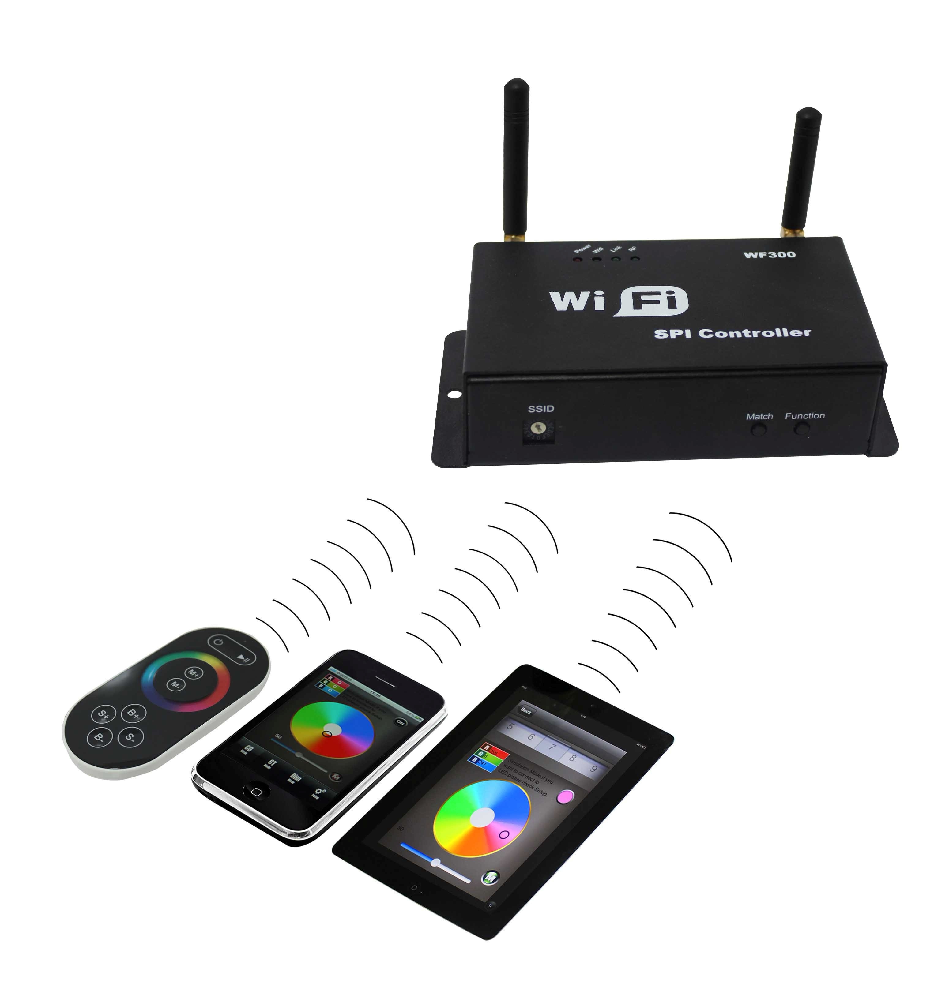
1. Product constitute
|
1. LED-WiFi Controller |
It is the core of product, responsible for receive control signal and control LED equipment. |
|
2. RF remote control |
In the condition of not use the mobile phone as remote control, you can choose RF remote control to control LED. |
|
3. A disk |
Include IOS operating system and Android operating system mobile soft. |

2. Summarization
LED-WiFi controller is following the traditional with infrared, RF technology controller foundation, it is birth of market and customer's demand, it is one type controller which integration the newest wifi technical in the market. It makes the LED control more convenience, more hommization. We can use an Android system or IOS system mobile phone to install control software, then it can control LED, this is the wishes of every customer.
Use WiFi technology can make our control range more wider, can get rid of narrow space constraint, in building can control more than 50m, in outdoor can control more than 100m.
In the condition of not use the mobile software, also can use the remote control to control, very convenience, bring many choices for you.
II. Technical Parameters
1. Remote control technical parameters
1:Working temperature:-20-60℃
2:Power supply method:AAA*3
3:Supply voltage:1.5V*3
4:Standby power:0.015mW
5:Standby current:3uA
6:Working current:200uA
7:Emission current:10mA
8:Remote control distance:about 30m
9:Standby time:6 month
2. Software technical parameters
1:Name:Magic Color
2:Runtime platform: Android version support Android system(better one can support Samsung,
HTC), IOS version support IOS system, equipment must have WiFi function.
3:Language: English
4:Category: communications
5:Free, green, no plug-ins
3. Controller technical parameters
1:Working voltage: DC5--24V
2:Output control: SPI signal output
3:Output current: 4A*3
4:Connect mode: SPI signal wires(DATA, CLK)
5:External dimension: L107*W65*H30(mm)
6:Receiving sensitivity: 802.11b DSSS(-5dBm),802.11b CCK (-10dBm),802.11g
OFDM(-15dBm)
III. Magic Color Instruction
1. WIFI Connect
After power on the controller, open the cellphone set of WIFI, search WIFI network, you will check WIFI equipment is named LN+number, for example"LN001", "LN003" and so on, as picture:

The number after LN is controller SSID code, same controller can set different code, when in the same network environment have many controllers, it can distinguish. About the SSID setting, will be in details below.
2. Software setting
After connect the WIFI, open the application enter the following interface:

Above picture "RUN" is enter remote control interface, before enter this interface, need to set the software parameter first. Click the "SETUP" in middle to setting.
At this moment it will enter below interface:

1: Dropped connect again button. When the cellphone use this software, because the lock screen or other
reasons result in WIFI can not remote, click this key, if connect successful, then shows
 , if connect fail, then shows
  .
.
2: Press the key sound.
3: Controller model choose.
4: Controller parameter setting.
This product model is WF300, so choose "WF300", and then it will enter below interface:

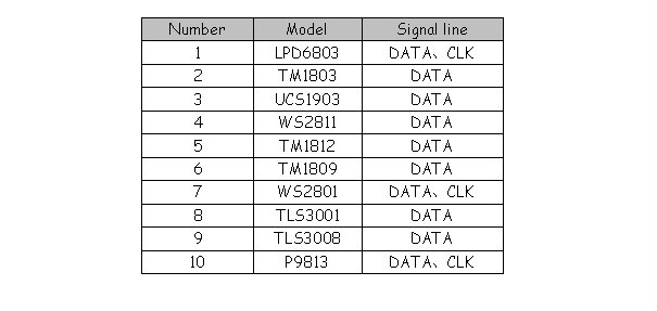
Setting adjustable control strip maximum support point(range 16~1024), strip IC model (10 kinds), strip RGB sequency. Because in the market, many strip the specificate is different, some the sequency is RGB, some is RBG, GRB and so on, so this setting method can suit for all have sequency strip.
3. Remote control
When have set up after the above parameters, click "Back" to return to the main interface, click "RUN" to control the strip, it will enter below interface:

When switch in this state, controller open; When switch in this
 state, controller off, and at this time it is locked state, unless on/off key, other keys can not use.
In the mode column, in total have 83 kinds of modes, the first 7 modes is static mode, at this time can through nether brightness slider to adjust the brightness of strip, in total 32 levels, other modes can not adjust brightness(remark: LD6803 strip, all modes can not adjust brightness).
Except the first 7 modes, others is all dynamic modes, at this time can through speed slider to adjust speed, in total 99 levels, the value is more big, the speed is more quick.
Play/Pause key can stop the running mode, just suitable for dynamic modes.
IV. LED-WiFi Controller Function Instruction
1. Working state instruction
|
Indicator light |
Function table |
|
Power |
Power indicator light, long-time bright shows power supply normally |
|
Wifi |
Free time long-time bright, have wifi data enter flicker, configuration wifi Ssid off |
|
Link |
Have wifi date enter, then flicker, no wifi data, then off. |
|
RF |
Have RF remote data or press key operate, then flicker, free time off. |
2. Setting SSID number
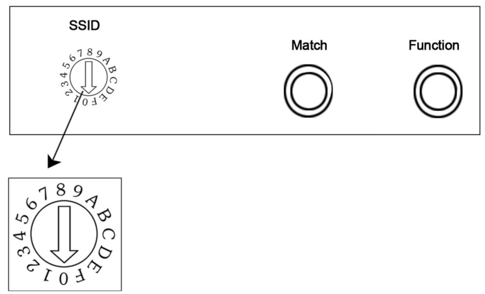
The dial code is used for setting LED-WiFi controller Ssid number, corresponding table as below. Form 0 to 15, have 16 code in total, so our Ssid number fasten to LN001 to LN016. That means use our product in same small area can set 16 mutual isolation LAN, once the dial code changed after switch was dialed, Ssid number immediately be modified, so you need to note that it need to search and connect again.
|
code |
SSID |
|
0 |
LN001 |
|
1 |
LN002 |
|
2 |
LN003 |
|
3 |
LN004 |
|
4 |
LN005 |
|
5 |
LN006 |
|
6 |
LN007 |
|
7 |
LN008 |
|
8 |
LN009 |
|
9 |
LN010 |
|
A |
LN011 |
|
B |
LN012 |
|
C |
LN013 |
|
D |
LN014 |
|
E |
LN015 |
|
F |
LN016 |
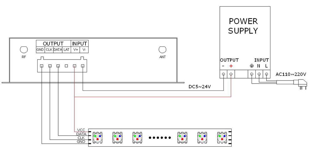
3. Connect LED, Power supply port
LED Strip according model connect corresponding port.
4. Match Key function
The first time use the controller and remote control, maybe because the controller address and remote control address is not match, it will cause the remote control can not control, at this time, it need to use this button to make this 2 address matched.
Use method: first, press the controller "Match" key, at the same time press any key of the remote control, more than 2s, now the remote control indicator light RF will flicker 3 times, release "Match" key, then finished.
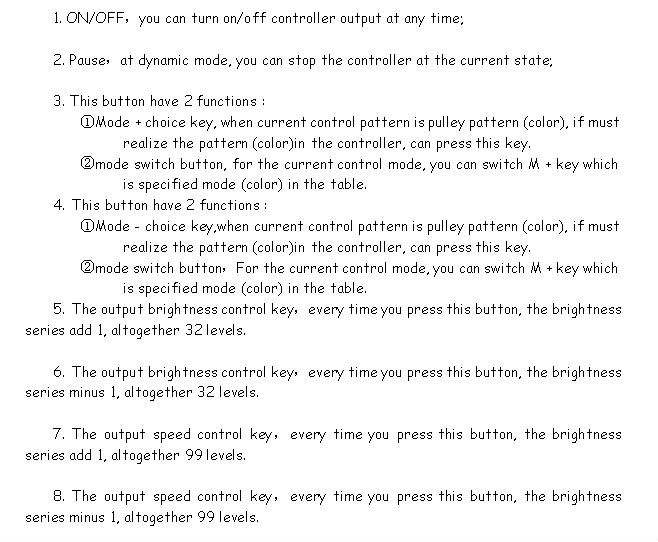
5. Function key function
“Function” key is a composite button, it have switch and mode change function.
Function instruction: long-time(more than 2s): on off;
Short press(less than 1s): mode change.
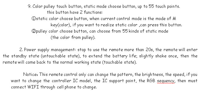
6. Remote control function instruction

1. Controller panel have 64 touch point, and the function as follow:
7. Controller built-in mode table
|
Modes |
Mode instruction |
|
1 |
Static red |
|
2 |
Static green |
|
3 |
Static blue |
|
4 |
Static yellow |
|
5 |
Static purple |
|
6 |
Static cyan |
|
7 |
Static white |
|
8 |
Red horse race to right |
|
9 |
Red horse race to left |
|
10 |
Green horse race to right |
|
11 |
Green horse race to left |
|
12 |
Blue horse race to right |
|
13 |
Blue horse race to left |
|
14 |
Red horse race lower curtain |
|
15 |
Green horse race draw curtain |
|
16 |
Three base color horse race brush forward direction |
|
17 |
Three mixing color horse race brush |
|
18 |
Three base color horse race brush draw curtain |
|
19 |
Three mixing color horse race brush lower curtain |
|
20 |
Seven-color horse race brush forward direction |
|
21 |
Seven-color horse race brush backward direction |
|
22 |
Seven-color horse race brush draw curtain |
|
23 |
Seven-color horse race brush lower curtain |
|
24 |
Three base color brush forward direction |
|
25 |
Three base color brush backward direction |
|
26 |
Three mixing color brush forward direction |
|
27 |
Three mixing color brush backward direction |
|
28 |
Seven-color brush forward direction |
|
29 |
Seven-color brush backward direction |
|
30 |
Three base color brush draw curtain |
|
31 |
Three base color brush lower curtain |
|
32 |
Seven-color brush draw curtain |
|
33 |
Seven-color brush lower curtain |
|
34 |
Three base color stroboflash |
|
35 |
Seven-color stroboflash |
|
36 |
Three base color jumpy change |
|
37 |
Three mixing color jumpy change |
|
38 |
Seven-color jumpy change |
|
39 |
Green-blue-yellow three color wave by wave running forward direction |
|
40 |
Blue-yellow-cyan three color wave by wave running backward direction |
|
41 |
Three mixing color three color wave by wave running forward direction |
|
42 |
Three mixing color three color wave by wave running backward direction |
|
43 |
Blue-yellow-cyan three color wave by wave running forward direction |
|
44 |
Green-blue draw curtain |
|
45 |
Blue-yellow lower curtain |
|
46 |
Seven-color wave forward direction |
|
47 |
Seven-color wave backward direction |
|
48 |
Blue trail backward direction |
|
49 |
Red trail forward direction |
|
50 |
Red trail backward direction |
|
51 |
Green trail forward direction |
|
52 |
Green trail backward direction |
|
53 |
Blue trail forward direction |
|
54 |
Yellow trail forward direction |
|
55 |
Cyan trail forward direction |
|
56 |
Purple trail backward direction |
|
57 |
White trail forward direction |
|
58 |
White trail backward direction |
|
59 |
Seven-color running trail backward direction |
|
60 |
Seven-color running trail forward direction |
|
61 |
Change color cyan-red-cyan forward direction |
|
62 |
Change color purple-red-purple forward direction |
|
63 |
Change color purple-red-purple backward direction |
|
64 |
Change color yellow-green-yellow forward direction |
|
65 |
Change color yellow-green-yellow backward direction |
|
66 |
Change color cyan-green-cyan forward direction |
|
67 |
Change color cyan-green-cyan backward direction |
|
68 |
Change color purple-blue-purple forward direction |
|
69 |
Change color purple-blue-purple backward direction |
|
70 |
Change color cyan-blue-cyan forward direction |
|
71 |
Change color cyan-blue-cyan backward direction |
|
72 |
Change color white-red-white forward direction |
|
73 |
Change color white-red-white backward direction |
|
74 |
Change color green-red-green forward direction |
|
75 |
Change color blue-red-blue backward direction |
|
76 |
Change color yellow-red-yellow forward direction |
|
77 |
Change color yellow-red-yellow backward direction |
|
78 |
Change color red-yellow-red |
|
79 |
Change color red-purple-red |
|
80 |
Change color green-cyan-green |
|
81 |
Change color green-yellow-green |
|
82 |
Change color blue-purple-blue |
|
83 |
Automatically play 8~82 |
V. Explain installed hardware
1. Install ANT
ANT's installation drawing: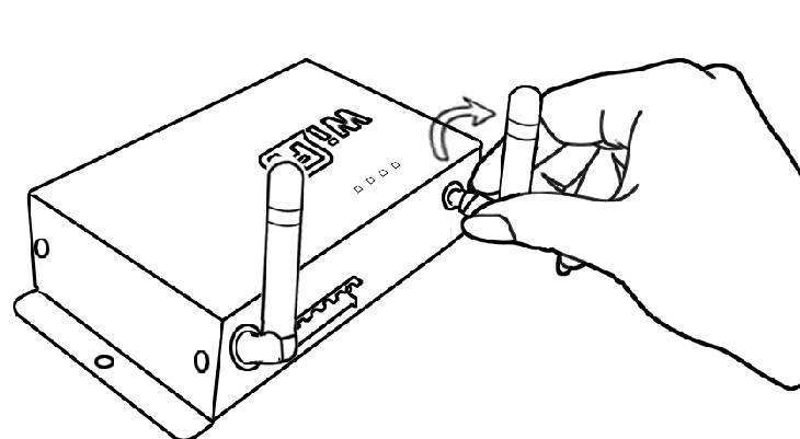 clockwise install WIFI antenna and
anticlockwise take down the antenna.
2. Install power supply and LED equipment
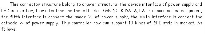

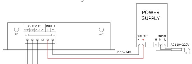
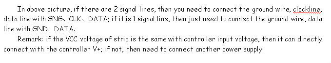
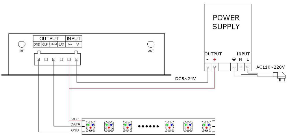
3. Connect single signal line strip condition