

WiFi Controller(can access route)
| Place of Origin | shenzhen |
|---|---|
| Brand Name | okled |
| Model Number | WF400 |
| Inquiry | |
Detailed Product Description
Product specification
Name:LED WIFI Controller
Model:WF400

I. Product Summarization
1. Product constitution
|
NO. |
Name |
Instruction |
|
1 |
WF400 Controller |
It is the core of product, is responsible for receiving control signal and controlling LED equipment. |
|
2 |
disk |
Include mobile software of IOS operating system and Android operating system |
|
3 |
manual |
Detailed instructions of product using methods |
|
4 |
USB cable |
Using when connected with computer |
2. Product summarization

II. Technical Parameters
1. Software technical parameters
1.1 Control software:
1. Name: Touch Home
2. Runtime platform: Android system (iphone, ipad), equipment must have WiFi function.
3. Language: English
4. Category: communications
5. Other: Free, no plug-ins
1.2 Configuration software
1. Name: WiFiManager
2. Runtime platform: Win 7/Windows Vista/Win2003/WinXP/Win2000
3. Language: English
4. Category: communications (USB)
5. Others: Free, no plug-ins
2. Controller technical parameters
1. Working voltage: DC5-24V
2. Working temperature: -20-60Ōäā
3. Working Power consumption: about 1.6W
4. Output: 3 channel common anode, Max. current4A/each channel, with over current protection
5. Packing dimension: L215 * W165 * H55(mm)
6. External dimension: L107 * W65 * H30(mm)
7. Controller weight: 340g
8. Remote control weight: 85g
9. Gross weight: 460g
10. Receiving sensitivity: 802.11b/g DSSS(-5dBm),802.11b CCK (-10dBm),802.11g OFDM(-15dBm)m)
3. Remote control technical parameters
1. Working temperature:-20-60Ōäā
2. Power supply method:AAA*3
3. Supply voltage: 1.5V*3
4: Standby power: 0.015mW
5. Standby current:: 3uA
6. Working current: 200uA
7. Emission current: 10mA
8. Remote control distance: about 30m
9. Standby time: 6 month
III. Instruction for use
Proper use of WF400 mainly includes the following steps:
Step1:Recognize and identify the controller interfaces
Understand the function of each interface on the controller, its basic usage and wiring. Refer to the controller interface instructions.
Step 2: Configure the controller
Through WiFiManager, you can configure various parameters of the controller, including the name, location, network, time, output type and so on, facilitate user to recognize and control. Refer to WiFiManager instructions.
Step 3: Install controller
Understand specific wiring of controller and installation requirements. Refer to hardware installation instructions of controller.
Step 4: Remote control
Describes specific use of touch remote control. Refer to remote control instructions.
Step 5: Mobile phone control
Brief description control method of mobile phone. Refer to TouchHome instructions.
1. Controller Interface Description
1.1 Indicator Status Description


Power: indicator bright for long time shows power supply is normal, otherwise the power supply is not normal;
WiFi: when connected with network normally, indicator flashes slowly, when the network is experiencing a problem, indicator flashes fast;
Link: If there is no operation, the indicator is off, when control with mobile phone, it flashes;
RF: If there is no operation, the indicator is off, when control with remote control, it flashes;
1.2 Interface Description


1. CONFIG
Communction interface that should be connected with computer, works with WIFIManager software, it is used for configuring the controller parameters, including working mode, WIFI network, the name of controller, controller location, output type, read the device serial number, etc.
2. Match
The key is used for matching the controller with remote control. The first time use the remote control or
change remote control, you need to use this button to match the remote control with controller, then
you can use touch remote to control the controller properly.
3. Function
Mode switch (short press for 1s): switch built-in mode of controller;
ON/OFF (long press for 3s) : turn on/off controller
4. Input/ Output

Input: V+: positive of power input
V-: negative of power input
Output: V+: positive of output
CH1: output channel 1 (RGB: R; CT: C; DIM: CH1)
CH2: output channel 2 (RGB: G; CT: W; DIM: CH2)
CH3: output channel 3 (RGB: B; CT: -; DIM: CH3)
5. ANT
ANT: WIFI antenna
RF: touch remote control antenna
2. WiFiManager Instruction for use
1. Summarization
WiFiManager setup software is connected with controller through host USB. It mainly used to modify the network configuration of the controller, select wireless network, switch network mode, modify properties, such as the controller’s name, location, type and so on. User can flexibly choose the wireless network, modify the information of controller.
2. Instructions for use
2.1 Install WiFiManager
Remove the disc include with the controller into disc drive. Open the disc and find “WiFiManager.exe” to install software.
2.2 Use methods of WiFiManager
Open WiFiManager, it appears interface as shown below (figure 3.1): buttons of window are gray, this is because the controller is not connected. After connecting the controller through USB cable, it will appear the interface as shown in figure 3.2. Then you can operate the controller.

Figure 3.1

Figure 3.2
1. name of controllers:
the name of current connected controllers, it can be modified in the settings
2. output type of controllers:
output type of current connected controllers, select the appropriate output type according to user’s lighting type, it can be set to three output types: three-channel, two-channel, single-channel. It can be modified in the settings.
3. installation location of controllers
This option displays the installation location of controller, it can be modified
4. networking methods
Connection mode of current connected controllers
5. serial number of controllers
Serial number of current connected controller, it can not be modified.
6. searching
Search available wireless networks. The results of searching will display on the area “8”, this is all currently available networks.
7. setting
Set the parameters of controllers. (for detailed description, refer to 2.3)
8. current wireless network
Wireless networks list of currently searching
9. connecting
Connected to the currently selected network. Click “connect” to join the current network, if the network is encrypted, it will prompt you to enter your password, if it is not, it will connected to this network directly.

Figure 3.3
2. 3 Descriptions of parameters in setting page (Figure 3.3)
1. WiFi working mode
Infra: Infra network, connect with existing wireless network;
Adhoc: Ad hoc network, you do not need to connect with an external router, use mobile phone to control the controllers directly.
(Note: Currently it only supports Infra mode)
2. SSID (suitable for Adhoc mode)
Under Adhoc mode, you can set SSID, under Infra mode, it is invalid.
3. Encryption (suitable for Adhoc mode)
Open network: No security
Encrypted network: support encryption such as WEP64/WEP128/TKI/AES etc.
4. encryption password (suitable for Adhoc mode)
Set the encryption password (at least 8 characters)
5. output type
User should select corresponding output mode based on the lamps:
WF400A: full color lamps, three-channel (default);
WF400B: color temperature lamps, two-channel;
WF400C: single color lamps; single-channel.
6. set the name of controller
User can set the name of controller according to their needs (up to 32 characters), this makes the controller more humane.
7. set the location of controller
Set the location of controller (up to 32 characters). User can set specific location according to their arrangement, facilitate users to identify the location of lamps.
8. selection of WiFi channel
User can select the appropriate channel according to the needs, generally it can be set to Auto.
9. time synchronization of controller
The controller time should synchronize with computer to ensure that the timer works properly.
10. OK/ Cancel
OK: confirm the operation, the setting will take effect;
Cancel: cancel the operation, the setting will be canceled.
3. Instructions for remote control


5. Mode description of controller
When you select a different mode, the output mode of controller is different, the working mode should be configured according to the type of strip. When using RGB strip, user should select working mode as WF400A; when using color temperature strip, should select WF400B; when using single color strip, should select WF400C. Specific mode table is as follow:
1. WF400A mode:
WF400A mode: When using RGB strip, user should select this mode. It can control all four-wire loop (common anode) LED full-color lighting products, extensive control: all limiting resistor LED lighting products such as: LED module of RGB full-color, LED light strip, SMD soft strips etc. In this mode, the controller can achieve dynamic changing such as: overall jumpy changing, gradually changing, stroboflash. With the phone control software, it can carry out self-defined color changes. Under jumpy changing and stroboflash mode, you can adjust brightness and speed, under gradually changing mode, you can only adjust speed, under static mode, you can only adjust brightness. The default mode table of controller is as below:

2. WF400B mode:
WF400B mode: When using double channel color temperature strip, user should select this mode. In this mode, the controller can achieve overall color temperature and brightness adjustment. With the phone control software, it can carry out self-defined color temperature and brightness changes. The default mode table of controller is as below:
|
No. |
Brightness proportion |
Remark |
No. |
Brightness proportion |
Remark |
|
1 |
C:0% W:100% |
Brightness is adjustable |
12 |
C:55% W:45% |
Brightness is adjustable |
|
2 |
C:5% W:95% |
13 |
C:60% W:40% |
||
|
3 |
C:10% W:90% |
14 |
C:65% W:35% |
||
|
4 |
C:15% W:85% |
15 |
C:70% W:30% |
||
|
5 |
C:20% W:80% |
16 |
C:75% W:25% |
||
|
6 |
C:25% W:75% |
17 |
C:80% W:20% |
||
|
7 |
C:30% W:70% |
18 |
C:85% W:15% |
||
|
8 |
C:35% W:65% |
19 |
C:90% W:10% |
||
|
9 |
C:40% W:60% |
20 |
C:95% W:5% |
||
|
10 |
C:45% W:55% |
21 |
C:100% W:0% |
||
|
11 |
C:50% W:50% |
|
|
3. WF400C mode:
WF400C mode: When using single color strip, user should select this mode. In this mode, the controller can achieve overall brightness adjustment. With the phone control software, it can carry out self-defined brightness changes. The default mode table of controller is as below:
|
No. |
Brightness |
Remark |
No. |
Brightness |
Remark |
|
1 |
1% |
Brightness proportion |
12 |
55% |
Brightness proportion |
|
2 |
5% |
13 |
60% |
||
|
3 |
10% |
14 |
65% |
||
|
4 |
15% |
15 |
70% |
||
|
5 |
20% |
16 |
75% |
||
|
6 |
25% |
17 |
80% |
||
|
7 |
30% |
18 |
85% |
||
|
8 |
35% |
19 |
90% |
||
|
9 |
40% |
20 |
95% |
||
|
10 |
45% |
21 |
100% |
||
|
11 |
50% |
|
|
6. Hardware installation description
1. Install ANT
ANT's installation drawing:

clockwise install WiFi antenna and anticlockwise take down the antenna.
2. Install power supply and LED equipment
This connector structure belong to drawer structure, the device interface of power supply and LED is together, four interface one the left side (CH3, CH2, CH1, V+)is connect led equipment,the fifth interface is connect the anode V+ of power supply, the sixth interface is connect the cathode V_ of power supply. According to the rated voltage of led lamp, we supply power to controller ,and the rated voltage of controller is DC5-24V. As follows:

3. RGB lamps connection diagram

When user’s lamp is RGB type, you need to set the controller type to WF400A through PC software, the output type is RGB, connect the lamp according to above diagram, then you can use it.
4. Color temperature lamps connection diagram

When user’s lamp is CW type, you need to set the controller type to WF400B through PC software, the output type is CW, connect the lamp according to above diagram, then you can use it. You can select built-in color temperature proportion of controller through the Function button on the controller or M+, M- button on the touch remote control, also can adjust overall brightness through B+, B- on the remote control or control through mobile phone software.
5. Single color lamps connection diagram

When user’s lamp is single color type, you need to set the controller type to WF400C through PC software, the output type is DIM, connect the lamp according to above diagram, then you can use it. You can select built-in brightness of controller through the Function button on the controller or M+, M- button on the touch remote control or realize dimming steplessly through mobile phone software.
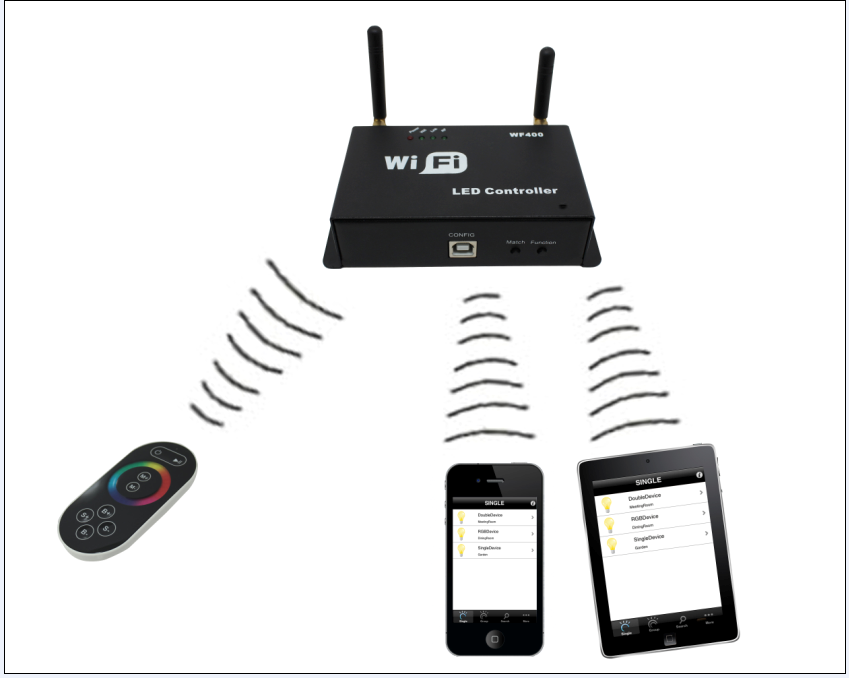
IV. System Application Diagram
When there are multiple controllers in user’s wireless network, the system structure is as shown in figure 8.1. User can control these controllers separately or in group. In a control system, it can accommodate up to more than 250 controllers, about control mode, please refer to “TouchHome” software instructions.

Figure 8.1
V. Notice
1. Please don't install controller in a seal off , high magnetic field or high pressure area;
2. In order to reduce the risk of fire disaster and device damage caused by short circuit , please make sure correct connection;.
3. Please do install controller in a well-ventilated area to insure appropriate temperature .
4. Installation position of controller should be as near as possible to the router so as to ensure controller normal working ;
5. Check out whether the supply voltage and power is in the range of controller required or not .
6. Before power on , please inspect the line is correct connection, and test it whether there is a short circuit ;
7. Any problem , please do not open the shell of controller .
8. This manual is only applicable to this model of controller, if there is an update without notice.
VI. Fault Analysis
|
No. |
Phenomenon |
Reason |
Solutions |
|
1 |
Load has no output |
1. out of power 2. output is overload 3. mistakenly connection |
1. check the power 2. increase power amplifier 3. check the connection |
|
2 |
Color is not correct |
Connection of RGB is wrong |
Check whether RGB connection is corresponding or not |
|
3 |
Indicator of remote control flicker |
The battery power is not enough |
Change battery |
|
4 |
With the voltage droping, the voltage is not uneven |
1. output cable is too long 2. output cable diameter is too small 3. controller or power supply is overload |
1. shorten the length of cable 2.use cable with large diameter 3. increase power amplifier |
VII. After-sale services
Within one year that you buy our products, if you operate correctly according to user manual, there is quality problem, we can provide free repair or replacement service, except for the following situations:
1. damage caused by misuse;
2. unauthorized disassembly, repair and modify circuit and incorrect connection;
3. damage caused by transportation, influent; damage caused due to earthquakes, fires, floods and other natural disasters.